I've been thinking for years about automating some of the hot air ducts on my heating system. People with hot water systems can put in separate zones. So I thought it would be nice to start with some way to control the heat through the ducts. Sure you can shut the hot air registers off at the floor. But these things get loose and floppy after awhile. Besides---who wants to run all over the house opening and closing registers. But inside each piece of ductwork is a damper that controls the amount of air to reach a register. For now I thought I would automate those---to take the place of the register. And for starters---I will just have all on or all off. So this is about the making of the prototype for a system that can eventually be very automated ---eventually leading to controls to allow for separate temperatures in separate room. So this is how I started.....
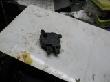 I happened to get a great deal on some small gear
reduction motors. I think they were used for electric windows in
cars. I started with an old piece of metal from a freezer door and cut a
small square to mount the motor too.
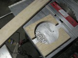
I then took a 1X4 of 3/4 wood strapping and cut 2
half circles. You will note they are spaced apart to make a 6 inch
circle. I wanted a space as they will be bolted together to draw
tight---like a clamp---on the 6 inch ductwork. One piece is a bit further
from the edge of the circle to the edge of the board. This is the distance
needed for when the motor and shaft are mounted. You will see as we go
along.
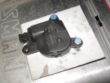
Here is the small square of metal with the motor
mounted to it. A hole was made in the metal for the motor shaft to
protrude through on the other side.
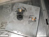
Here is the other side showing the motor
shaft.
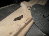
I had was trying to figure how to join the motor to
the damper flap. The damper is on the right. I took it out of the
ductwork for now. You can see where it has a nut to hold it in the hole in
the dict. It doesn't not go through both sides so depends on the nut to
keep it fairly straight in the duct. The shaft the nut is on is flat on
two sides. So I thought I would flatten a piece of tubing to fit it.
Then on the motor side there are groves inside of the motor shaft. I would
shape the tubing to be a thin sliver of metal to slide into the
grooves.
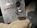
Here the tubing is flattened onto the damper shaft
but is too wide to fit into the motor shaft so will need to be
shaped.
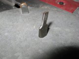
As the tube was ground down it split into two thin
pieces---but would now fit into the grooves of the motor shaft.
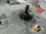
Here I tested it but just felt it was too flimsy
and might wander a bit and not hold the damper exactly where I wanted it.
So I scrapped this idea.
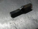
This was plan #2. I know it would take a bit
more time as I had to drag my welder out. But the result was much
better. this is a tad dark to see...but on the left is a piece of square
3/16 steel shaft. The slots in the motor shaft take a 3/16 square shaft
into the middle of them and are very tight around it. On the other end is
welded a 1/4 treaded coupler that will screw onto the damper shaft and up tight
against the damper bolt. This is MUCH better.
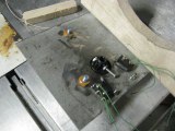
Here the metal and motor are mounted to the 1/2
wood circle. It's a tad hard to see---but I have drilled a small hole
through the base of the motor shaft. It's plastic and drilled
easily. Through it I bolted a small 4-40 treaded machine screw that
protrudes ad the shaft turns. Mounted on each side are lever switches
(sometimes called snap switches) that activate when the screw hits them.
This allows the motor---and damper---to turn to the closed position and
stop. When the screw hits the switch it opens it up and stops the power to
the motor. As it opens in on part of the switch---it closes in
another---and sends a signal to activate an LED light to signal that the cycle
is completed in that direction. The a switch is thrown from the control
area and it cycles 1/4 turn back until hitting the other switch and stopping in
the open position.
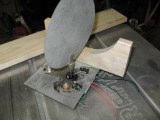
Here it is being tested with the damper flap on
it. This is how it will mount to the 6 inch duct pipe---only the damper
will be inside while the motor is outside.
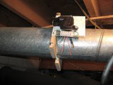
The unit is now mounted to the duct work.
Holes were drilled through the wood to take two rods of 6-32 thread--with
washers and nuts at each end to tighten it all in place on the ductwork.
The motor shaft snaps onto the square stock that was threaded to the
damper. There is a small lever of steel that went on the damper shaft to
show it's position inside. The steel was loose so even though it looks
slanted to the right a little---it really is up and down to depict
closed.
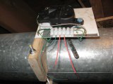
This shows a small terminal strip that was added to
make it easy to wire a cable to or to take off to repair or perhaps put
somewhere else at a later time.
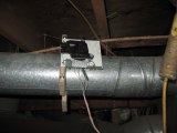
Here a temporary cable is attached to lead upstairs
to the room it controls. 6 wires are needed. Two power the motor one
way and two power it the other. Then two feed the 2 LEDS to show when it
has finished a cycle.
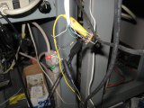
This is about as Mickey Moused as you can
get. I have power from a battery going to a DPDT switch. There are
two LEDs temporarily soldered to the lead in wires and resistors to lower the
amperage to them. One light is green for when it has reached "open" and
the other is red for when it reaches "closed."
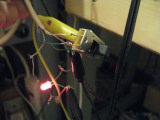
Here the power has been applied---the switch
thrown---and the motor and damper cycled to the close position and turned on the
red LED.
Now to make a few more of these. This was a prototype so I wasn't sure what the final materials will be. The wood looks kind of amateurish---but then again---it clamped really well. Maybe I'll just put the paint to it all later. Plans are to later incorporate room temperature sensors and a master setting that will open and close air flow as needed. But for today--this was just the first baby step.