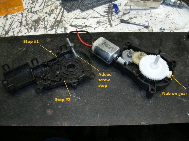
 It all started with a neat little gear driven motor I found at Electronic Goldmine's site. They sell all kinds of new and surplus "stuff." With it apart you can see a sort of nub on the far right of the big gear. There are two spots in the other half of the housing that the nub hits and stops the gear. The motor apparently doesn't develop enough torque to do any damage when it is stalled like that.
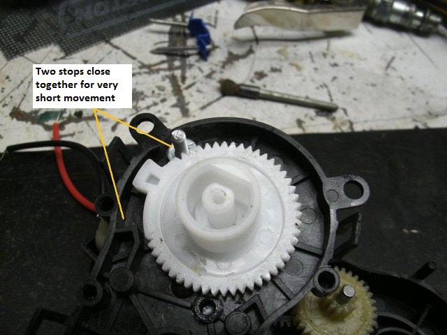
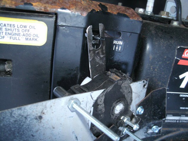
This shows where I added a screw for another stop. Before it cycled about 320 degrees. With this new stop it will move just a fraction of that. The nub will travel from the original stop #1 to my new stop---the bolt.
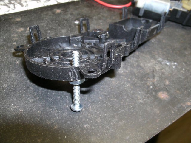
The bolt is bolted so as not to protrude through the other half of the case where a round wheel is attached and rotates.
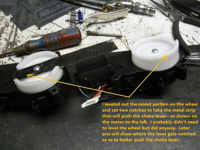
This shows how a lever was added to the gear motor. The motor on the right is untouched but the one on the left has been modified. Although I probably didn't have to level the plastic wheel, I did. Then I cut two notches to hold a thin piece of metal and secure it with the center screw that was already there. Later you will see where a notch was made in the metal to accommodate moving the choke lever.
Don't try to figure the mounting out. I tried multiple ways to mount it and ended up hacking up a lot of the motor case not to mention sheet metal brackets attached to other brackets to get just the right angle, as the lever rotated, to move the choke. I'm sure I could have found a better and neater way to mount it. But for now---it is what it is.
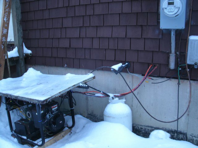
Pay no attention to the propane tank and line. This is to show the CCTV camera mounted on the house and aimed at the generator. There are also 2 heavy cables that go to a deep cycle battery inside---to offer full cranking power to the starter. Other wires lead in with them and the orange wire is the AC going from the generator into the house.
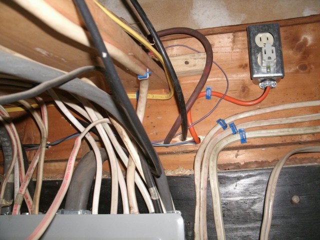
This is the corner of my cellar where my fuse panel is located and where the wires from outside come in. The orange wire is the AC from the generator and only feeds one 120v duplex outlet for now. There is a shelf above that holds the deep cycle battery.
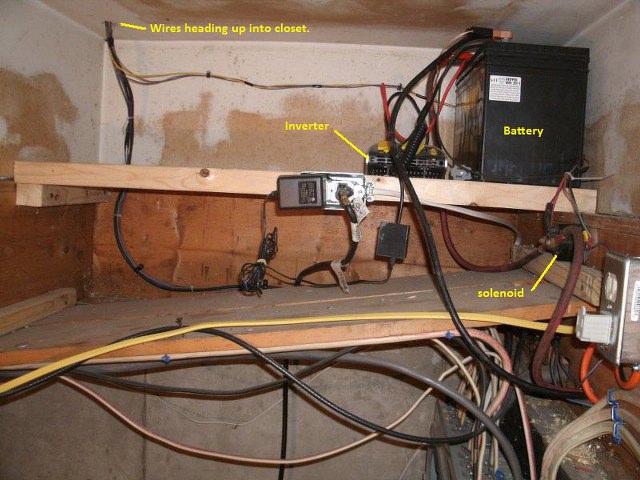
This is a bit of a mess and there are lose wires that go to other things. But this shows the battery and the red cable that runs from it---through a solenoid---and outside to the starter. There is also a small inverter beside the battery and another duplex outlet for a back-up lighting system----but nothing to do with this project. All of the wires for this project come together in the left corner and feed up into an unfinished closet.
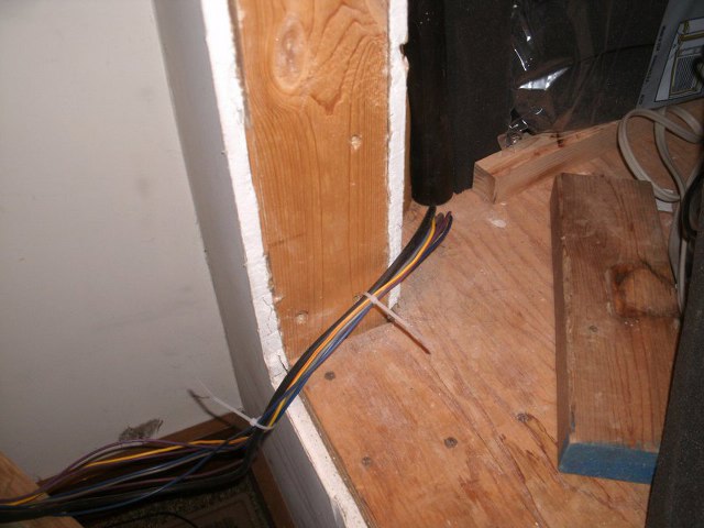
Here are the wires and CCTV cable coming up through a hole in the unfinished closet. The closet is about a foot off the floor----in order to give head clearance to the cellar stairs below it. So from here the wires just sneak around the corner and will eventually run under a window sill.
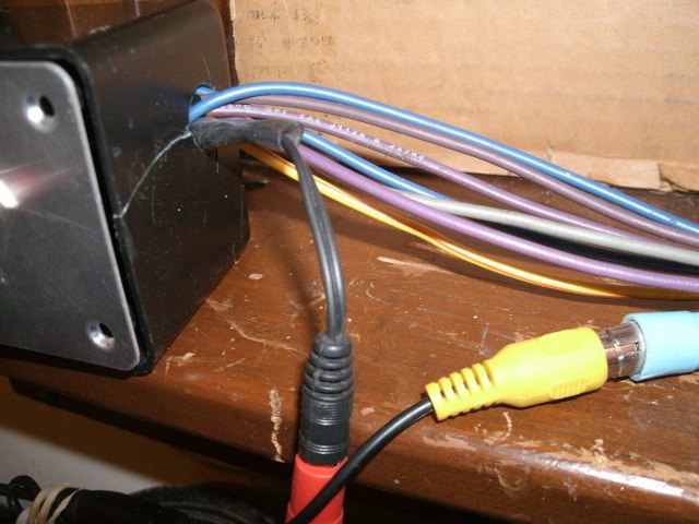
Here the wires feed into a Radio Shack project box of about 2.5 X 5 inches.
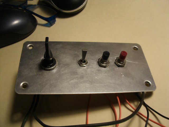
The project box starts by taking the face plate and mounting the controls. From left to right are.....A DPDT spring return switch to choke and unchoke the engine. Left chokes it...right unchokes it. The next lever is the on/off for the camera and monitor. Next is a black push button to start the engine. Last is a red push button to stop the engine.
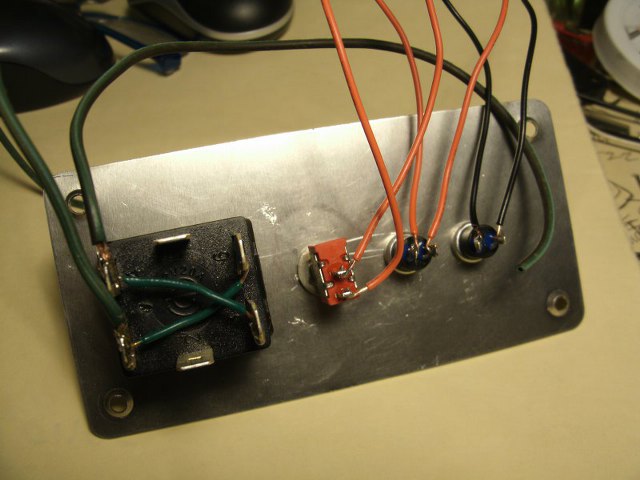
Since the switches will be wired in with the 8 wires coming from outside----short pieces of wire are attached to each lug on the switches. The large left switch is the DPDT. Two wires go to on a set of end contacts. Those will be for positive and negative voltage. Crossover wires swap the voltages to the other far end of contacts. When the motor is attached to the center contacts it will receive voltage when toggled one way---and then reversed voltage when toggled the other. This makes for the forward and reverse on the motor controlling the choke.
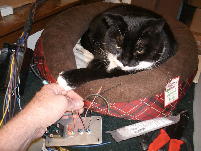
Now it's time to wire nut everything together. The leads from outside are fed through the project box and then connected to the appropriate switch on the face plate. Funny Face the cat thinks it's time to play as he hooks his "dad's" hand with a claw.
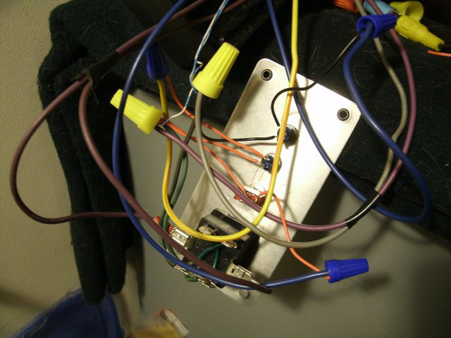
Everything is wired. Hmmm---but was the orange wire supposed to go to the blue---or was it the purple. Grubby had better check it all again.
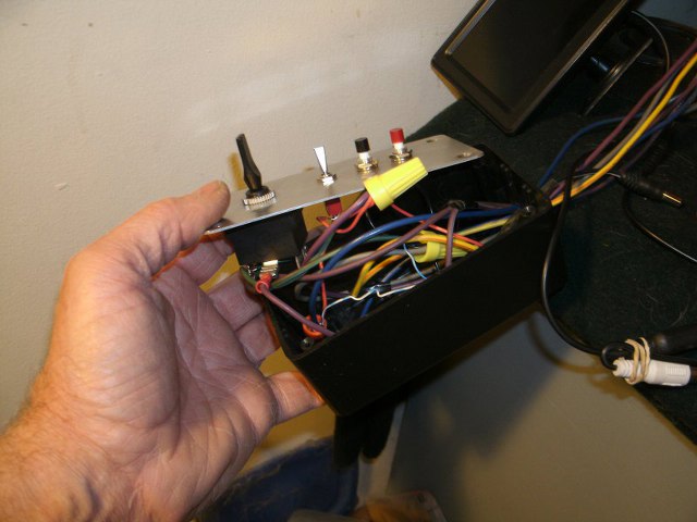
Well everything is correct now----but a bit tight to squeeze into the box. There is a spade lug on the toggle switch for the motor. It was too long and hit the bottom of the case. So in the pic you can see Grubby bent it to go sideways. But then it hit the side of the case. After much bending Grubby got it all to go into the project box.
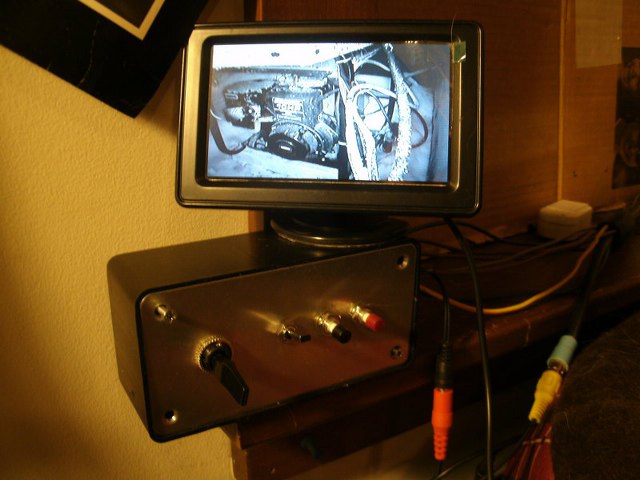
Here it is being tested with a small LCD monitor. You can see the outside engine at night, just fine. Later Grubby will mount the control box under the sill and the little monitor on top.
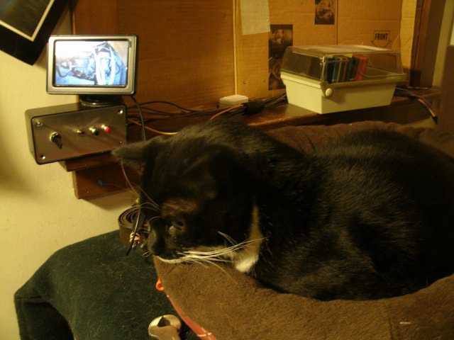
The window is blocked off with cardboard for now. But even with the A/C installed in the summer the box and monitor should not be in the way. But Funny Face isn't impressed with his new TV to watch. Nothing is happening. Guess he'll have to do what he does best---sleep and shed hairs.
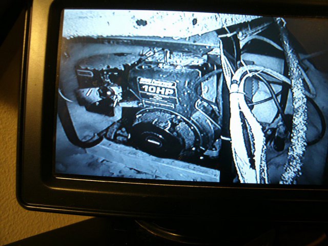
A close up of the monitor shows the engine. The fuzzy stuff around it and on the cables is snow from last night. The night vision is very good. Although the choke isn't that easy to spot while standing still----you quickly pick up on it as it moves. I may paint it white at a later date.
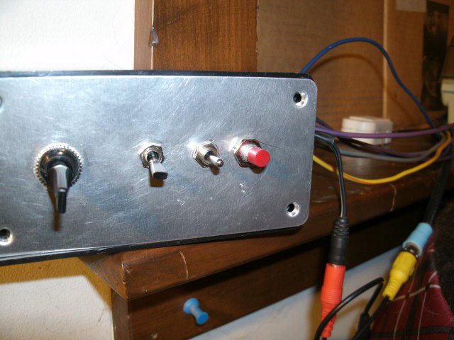
One last change was made to the controls. Grubby didn't like the start and stop switches being so closed together as they were both push button switches. Grubby worried that he might hit the Start button while the engine was running. So the black push button was replaced with a spring loaded SPST lever switch that has to be pushed up to start the motor. So that's it for this project. Hope it inspires others to try something similar. I LOVE being able to start my generator from inside now!!
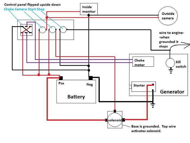
Here is the schematic of what I did----if anyone is interested. Of course where you see the "ground symbol" is the same as having a wire go to the negative terminal on the battery.